Siemens S7 200 Software

- Siemens S7 200 Programming
- Plc Siemens S7 200 Software
- Siemens S7 200 Software Download
- Programming Siemens S7 200 Software
Siemens S7 200 Programming
10 - SIMATIC STEP 7 - 200 Data Loggin 11 - SIMATIC STEP 7 - 200 MicroWIN - Installation (Free Download) 12 - SIMATIC STEP 7 - 200 MicroWIN - Activation (EKB Install).
Rating ( 80% score) - 1 vote S7-200 PLCs are built very compact and powerful: The SIMATIC S7-200 Micro PLC is fast, communication-capable and highly productive in real-time mode. The S7-200 Micro PLC from Siemens can be used as either a stand-alone Micro PLC solution or in conjunction with other controllers.S7-200 PLCs are built with two different generations of CPUs. Figure 1 displays different categorized models of S7-200 PLCs based on their CPUs. Figure 2 illustrates few different models of CPU 21X and 22X PLCs. Thus far, S7-200 is produced with 10 different CPU types. Figure 2 Figure 2 illustrates 4 typical models of 22 X series – from top left CPU 221, CPU 222, CPU 224 and finally CPU 226 Reminder Production of CPU 21X is discontinued, and since CPU 22X and SIPLUSE 22X are physically smaller with higher clock rate compared to 21X, they are the models mostly used in industries nowadays. The former CPUs have some digital I/O ports on board.
To solve the problem just download Siemens from Step7 trial version version 5.6 and install it on Windows10; the installation of Step7 v5.6 overwrites everything you need for the PG / PC interface. Now you can choose interfaces with Microwin, and finally go online with the PLC S7-200. To program the Siemens S7-200, you need Siemens MicroWin programming software. This is not the same software as used to program the S7-300/400 series. For the programming interface device, there are several different ones.
SIPLUSE 22X models are designed to withstand temperature ranges from 25C to 70C and function in Hydrochloric and Sulphuric chemical environments. In order to use a PLC to control a process, it must be hardwired to power supply and some field devices. Figures 3 and 4 display how two different models of SIMATIC S7/200 families can be hardwired to input/output devices.
As an example, CPU 221 DC/DC/DC is supposed to be energized by a 20.4 to 28.8 VDC power supply, it has 14 DC inputs and 10 DC outputs. See Figure 3.
Plc Siemens S7 200 Software
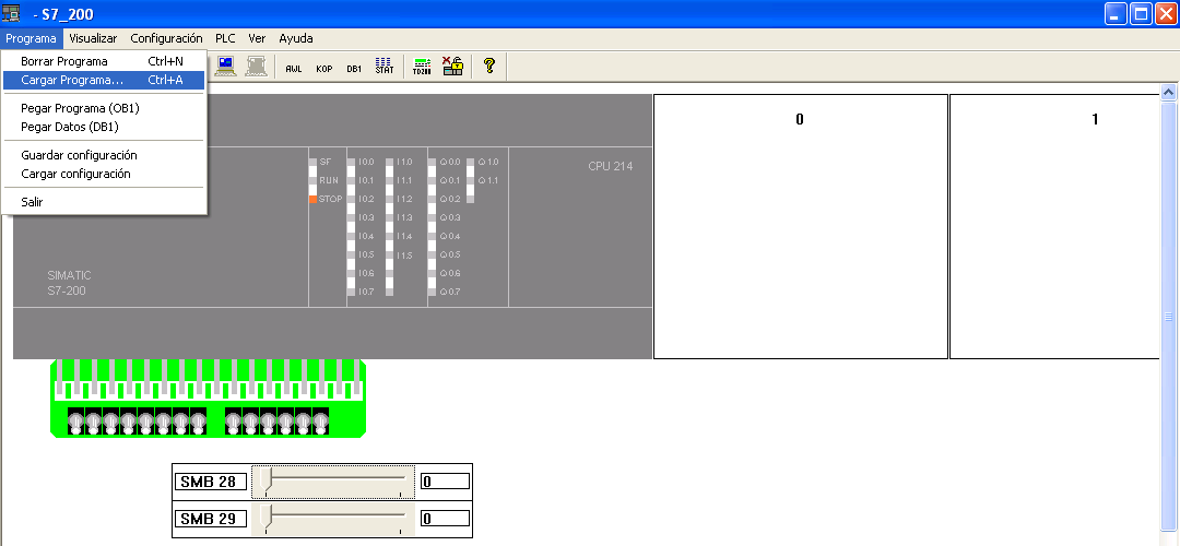
On the other hand, CPU 222 AC/DC/RLY (means PLC is supposed to be energized by 85-264 VAC mains power source @ 47-63 Hz), it has 8 DC inputs and 6 relay outputs. See Figure 4. Figure 4 displays I/O, power supply and DC sensor supply section of S7-200 model pictured in Figure 3. In figure 3 there are bunch of LEDs which inform the operator what is the working condition of PLC in use. The meaning of any led is turned on/off is as following Status LEDs: SF: System Fault, RUN: PLC is executing a program STOP: standby mode. I/O LEDs: turns on anytime, each input or output port is activated. TERM SWITCH: (top right): when mode switch is on “RUN”, position, CPU executes the prepared software.
It combines analysis functions with an interactive display that presents analytical results directly within the context of the building model. Check out the upcoming Revit 2014 BPA related features. Autodesk Ecotect Analysis is an environmental analysis tool that allows designers to simulate building performance from the earliest stages of conceptual design. Autodesk ecotect analysis download. Downloads: Vasari Software and Dynamo version 0.6.3 included MIRROR 1: MIRROR 2: (Vasari setup large than 2gb, I can only use my storage in Fshare and Pcloud to upload this ) (If want to boost your download speed, getlink in Ecotect 2011 MIRROR 1: MIRROR 2.
Langkah 2: Download driver terbaru untuk printer yang Anda miliki dan install pada PC Windows 10 yang Anda kehendaki. Cara menginstal printer. Jika metode koneksi otomatis ( auto connect) tersedia, pilih metode tersebut.
Siemens S7 200 Software Download

Programming Siemens S7 200 Software
CPU “ STOPS” execution when switch on stop position. And finally when switch is positioned on “TERM”, PLC operator is ready to choose the PLC’s operating mode. POT1, POT2: analog potentiometers to control analog sensor settings (top right). M/L (output DC Sensor Supply) terminals: PLC provides 24 VDC power for input sensors or expansion modules (280 MA). RS232 Port: is used to connect PLC to a PC and download programs.
Figure 5 In Figure 5, under little access door indicated by number “1”, these facilities are located: Mode selector switch (RUN/STOP), analog adjustment potentiometer(s), and expansion port (for most CPUs). Mode selector switch STOP, TERM, RUN function as it was mentioned for CPU 214.Status LEDs: System Fault, RUN, STOP also functions as explained already.Section indicated by number “2” can accommodate an optional cartridge: EEPROM, Real-time Clock battery. The “ Analog adjustment” can be used to increase or decrease some values related to PLC’s Timer or Counter set values.
When the POT is turned around, it does change the numerical analog values related to set values or limits inside the special section located in PLC’s memory. Optional Cartridge can be used to transfer program from one S7-200 to another S7-200 one. This cartridge is usually an EEPROM type of storage device.For S7-221 and S7-222 there is a real-time clock with battery backup available (can be placed inside of the cartridge socket).
The battery provides up to 200 days of data retention time in the event of a power loss. The S7-224 and S7-226 have a real-time clock built in. Another cartridge is available with a battery only. Figure 6 displays different configuration of SIMATIC S7-200 PLCs.
SIMATIC S7-200 Function modules: SIMATIC S7-200 has a consistently modular design. In addition to expansion and communication modules, the modular system provides a range of specific expansions for positioning, weighing technology and temperature measurement. Expansion modules contain additional inputs and outputs. These are connected to the base unit using a ribbon connector.


